Rgb Cat Lamp Hack
RGB Cat.
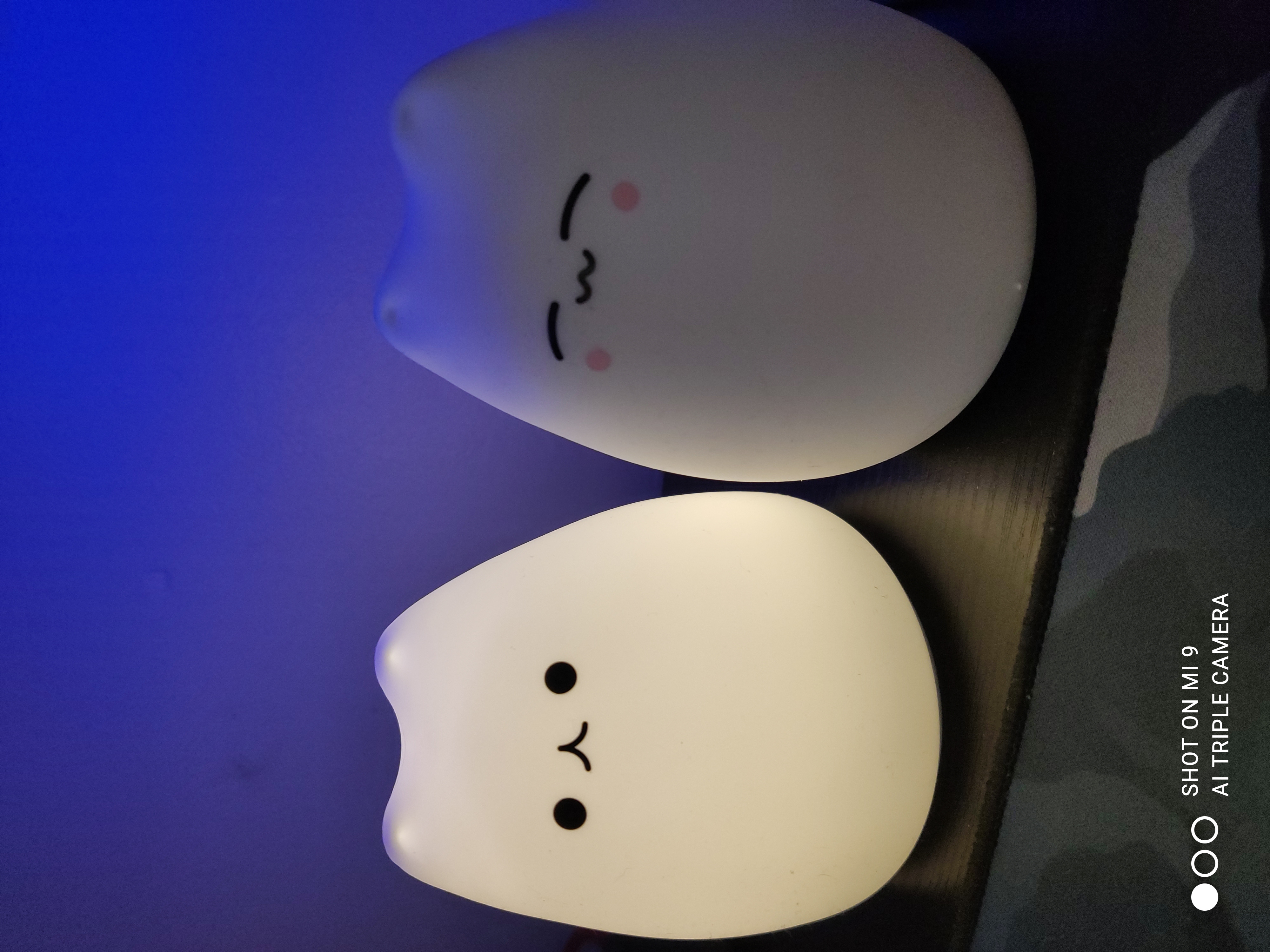
I was browsing through eBay the other day and discovered a silicone cat lamp that I thought would be a neat idea for a present for somebody. The device is chinese made so I am unsure on it’s true purpose but due to the nature and behaviour of the device it looks like some sort of night light aimed at children.
I got two with two different faces, thats the only difference between the two.
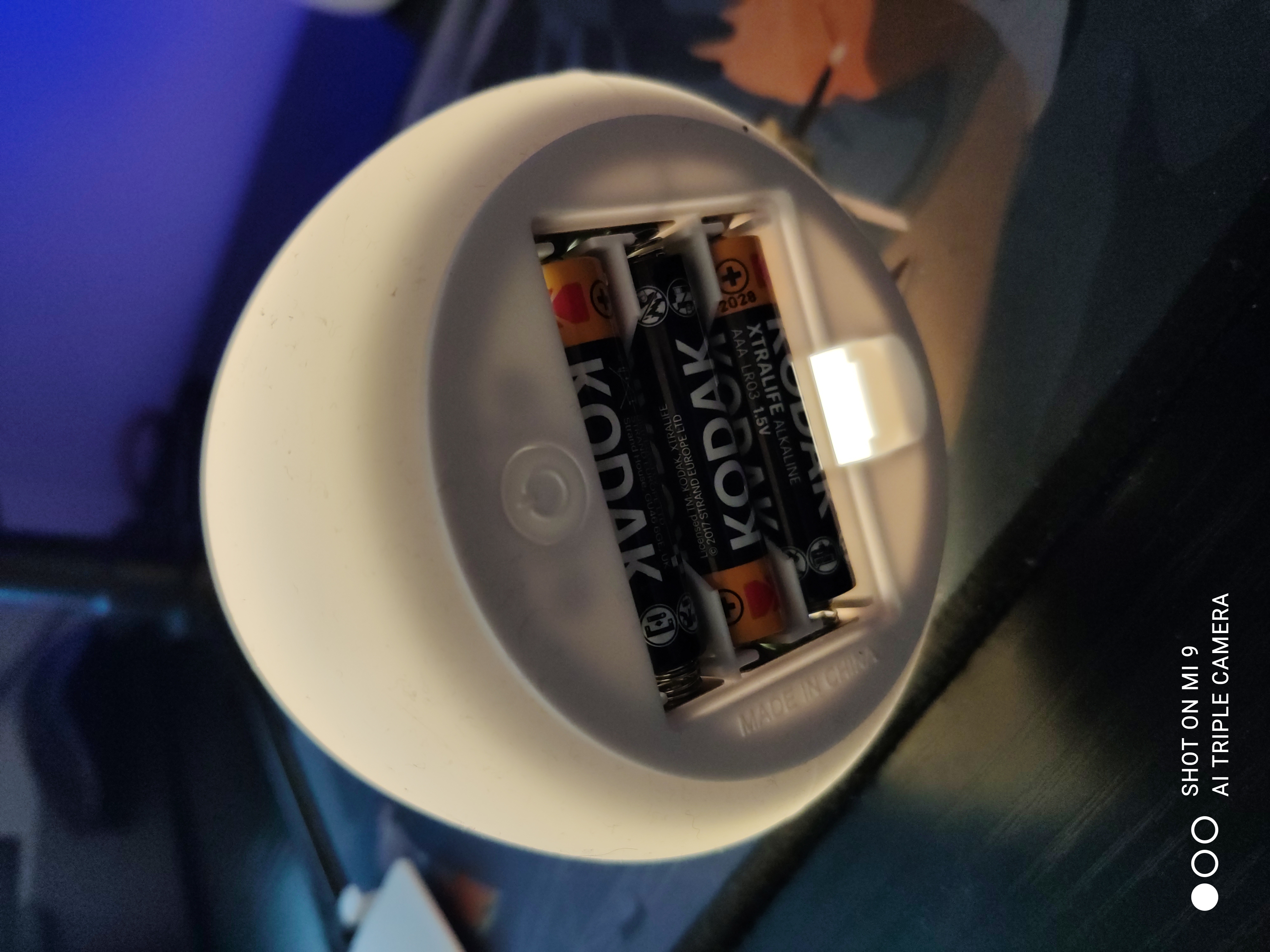
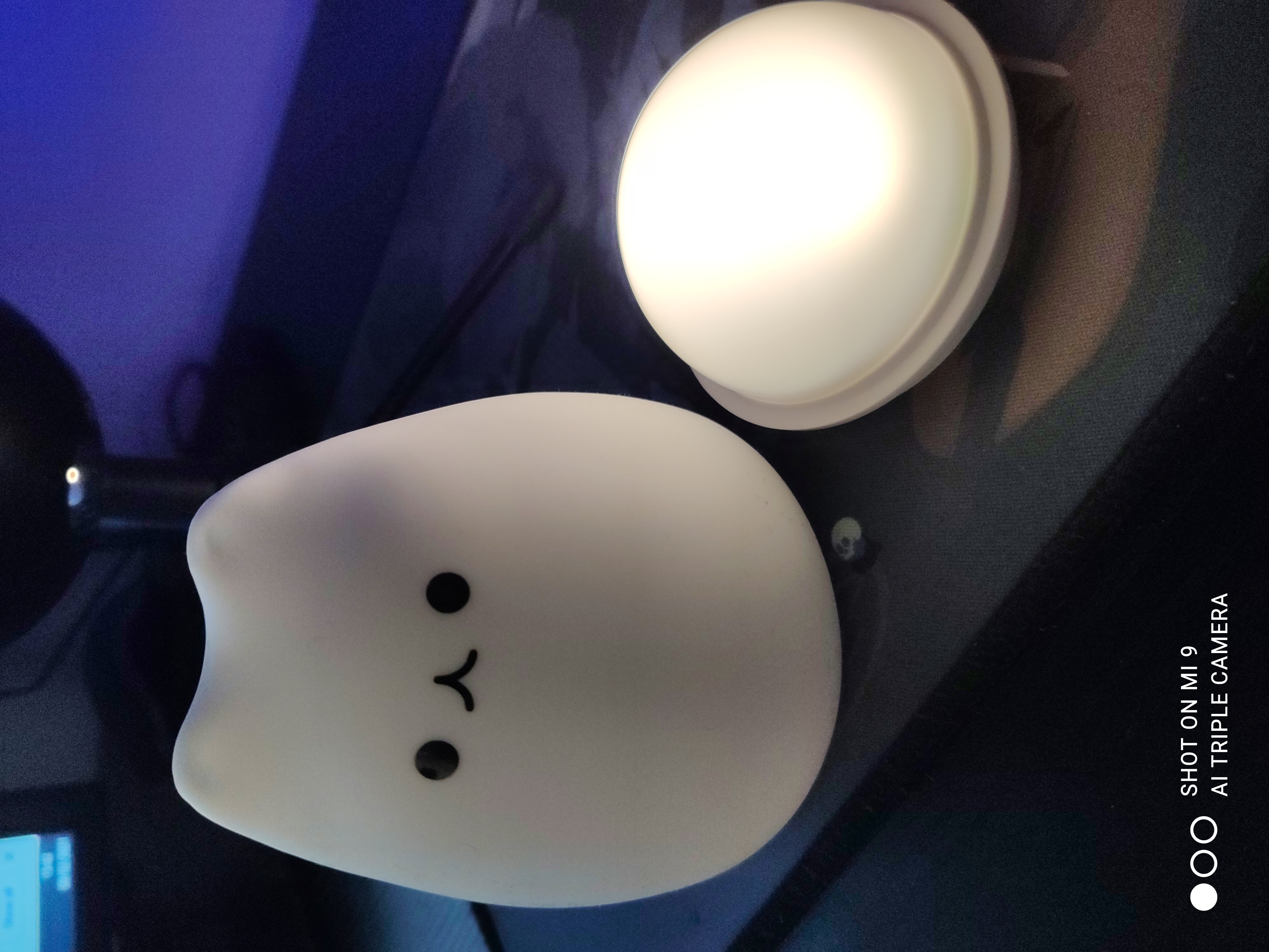
Taking a look at the device it’s battery powered and has two functions, one is just being on and another is when the device is tapped it cycles through a small amount of colours.
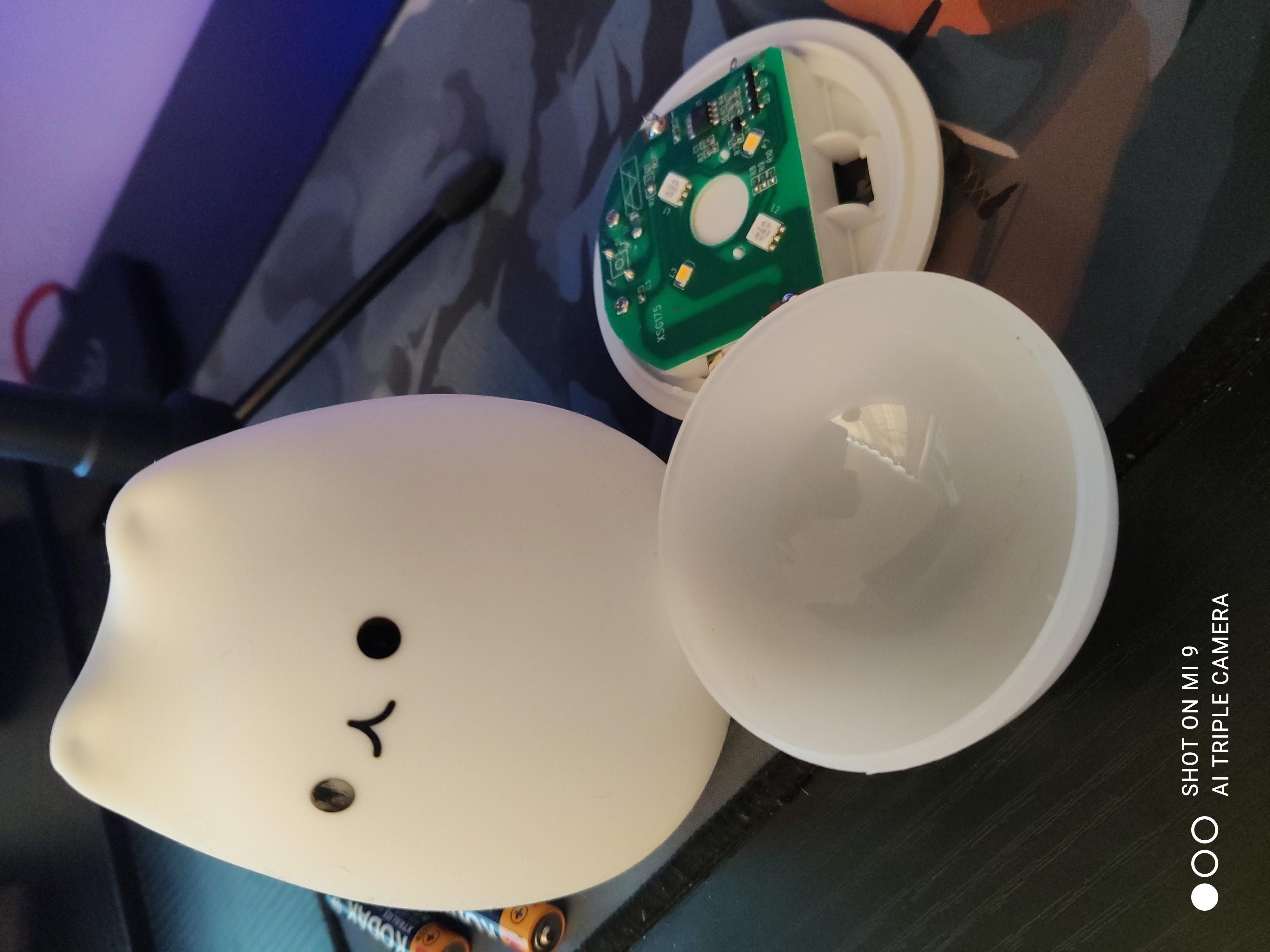
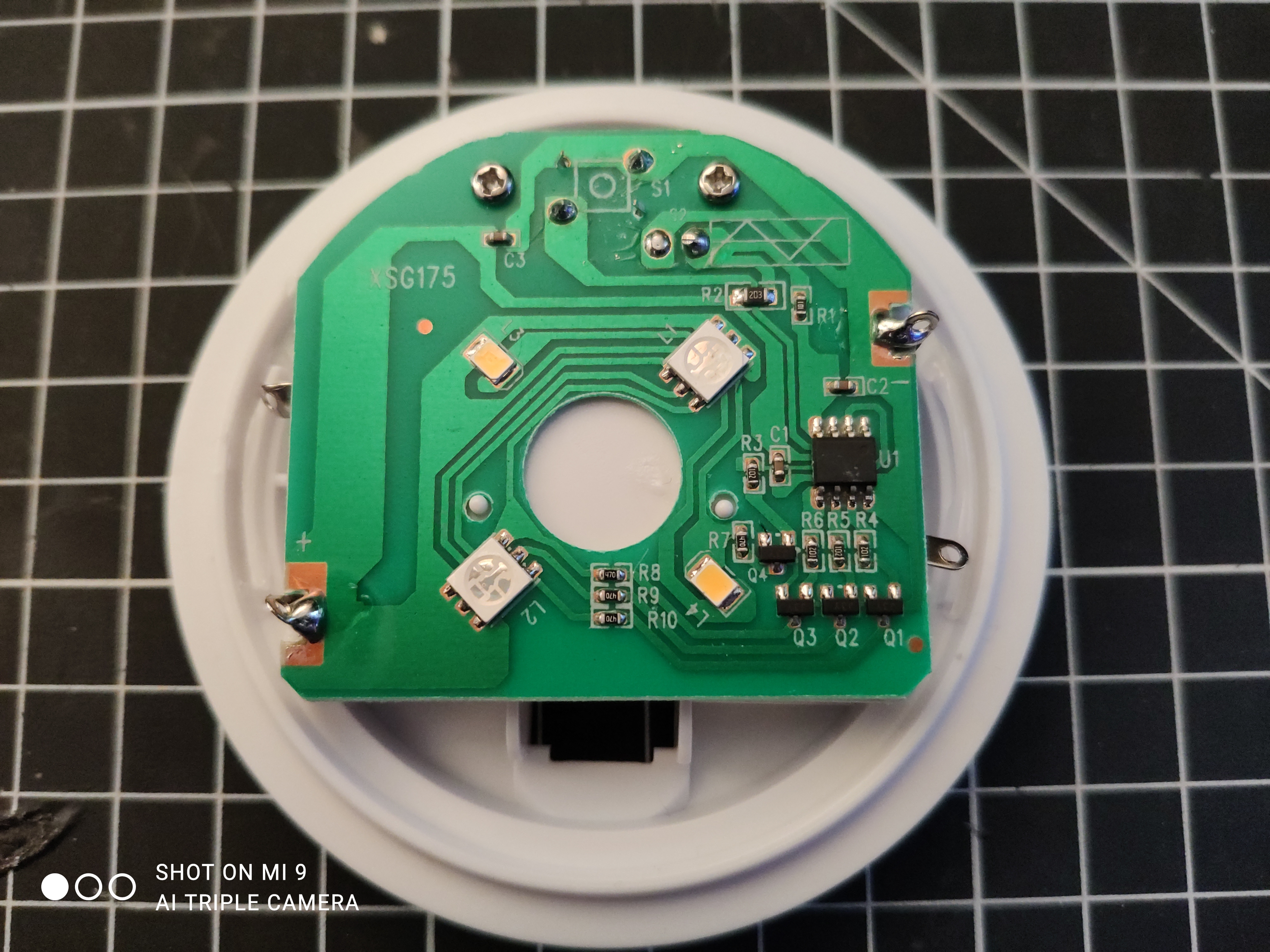
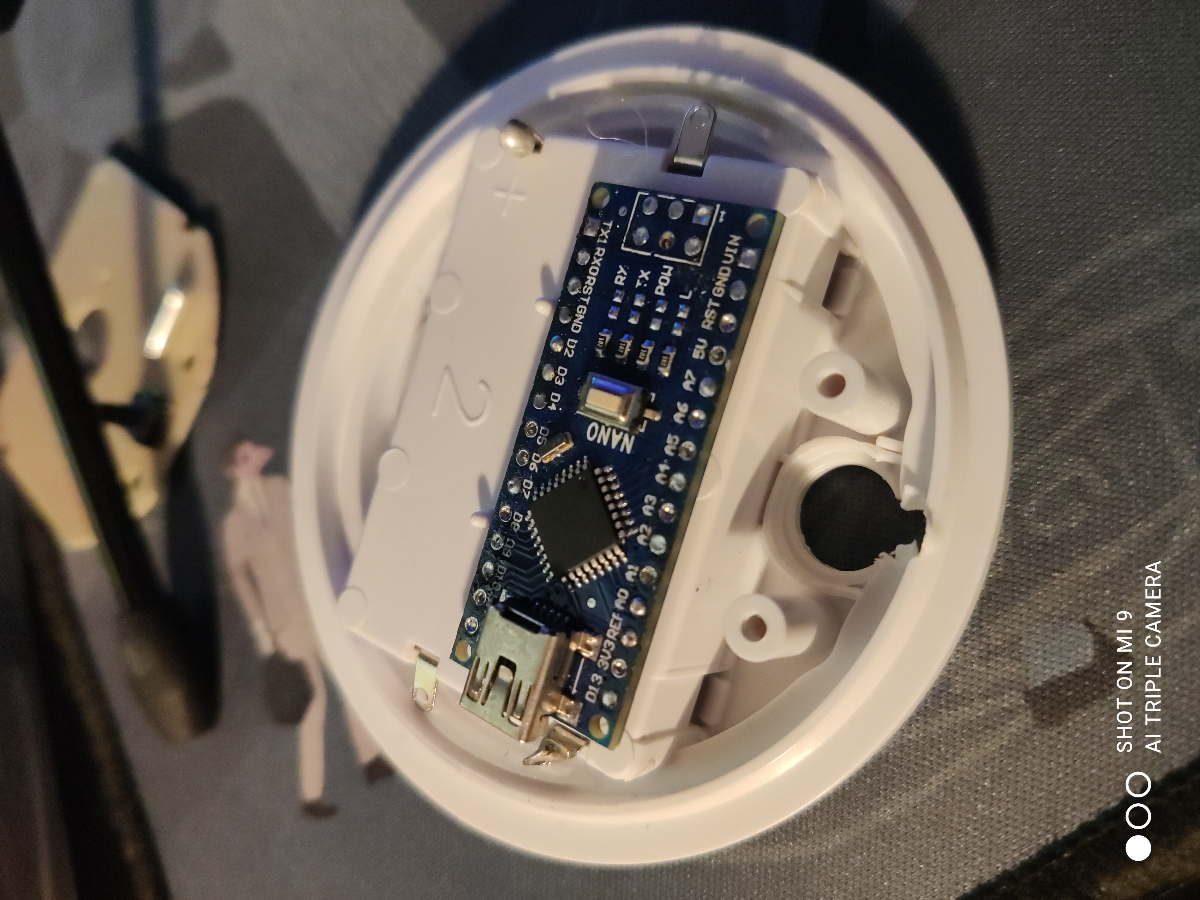
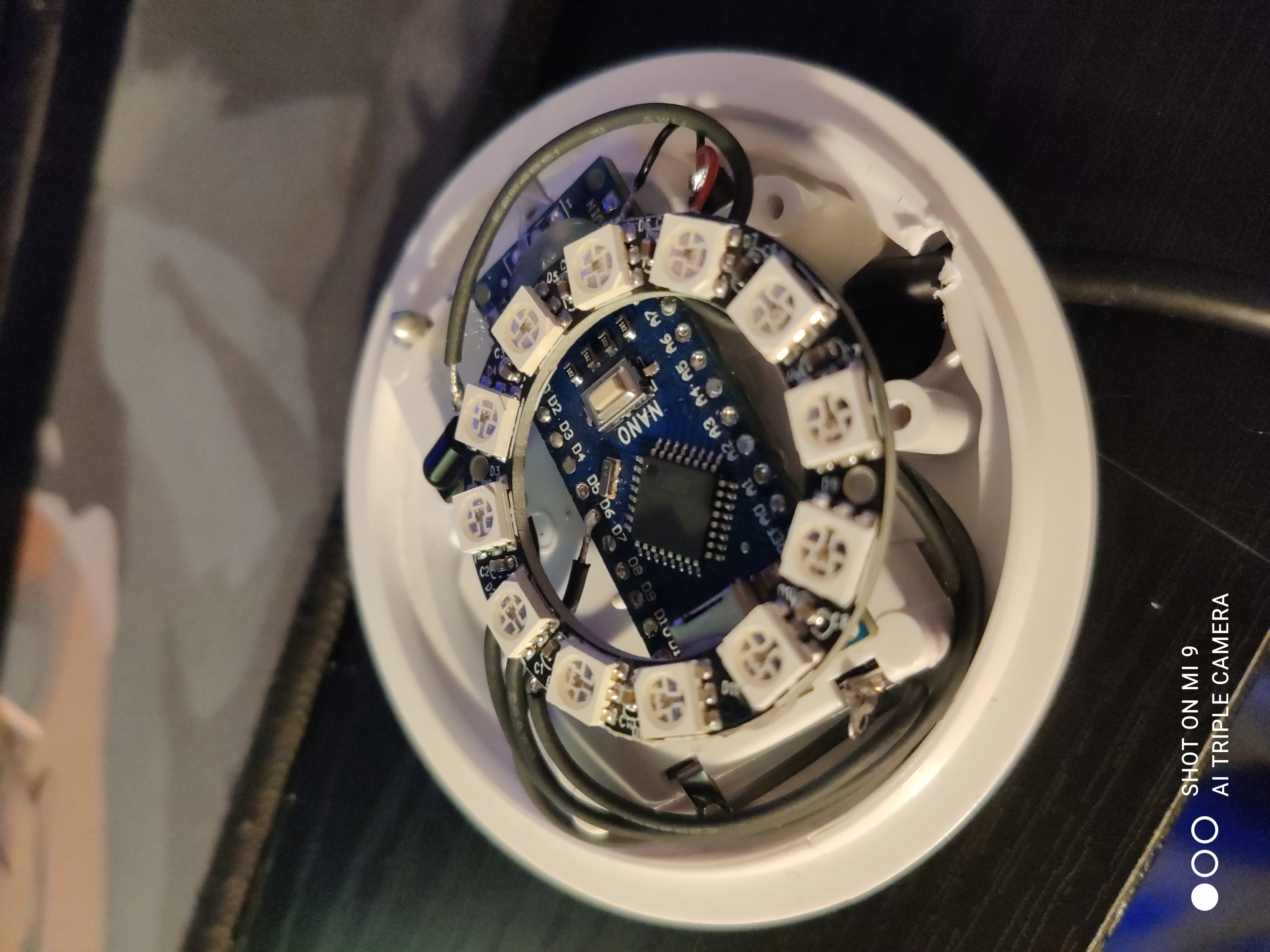
The silicone top comes off fairly easy revealing a small dome which when also removed reveals the circuitry inside.
My plan is as follows:
- Change the device to be USB powered instead of battery power (who likes changing batteries?)
- Be controlled with a simple IR remote that comes with most LED strips these days thus adding the functionality to change colours, brightness and turn the device off without hitting it.
- Be able to fit all these components inside away from the end user.
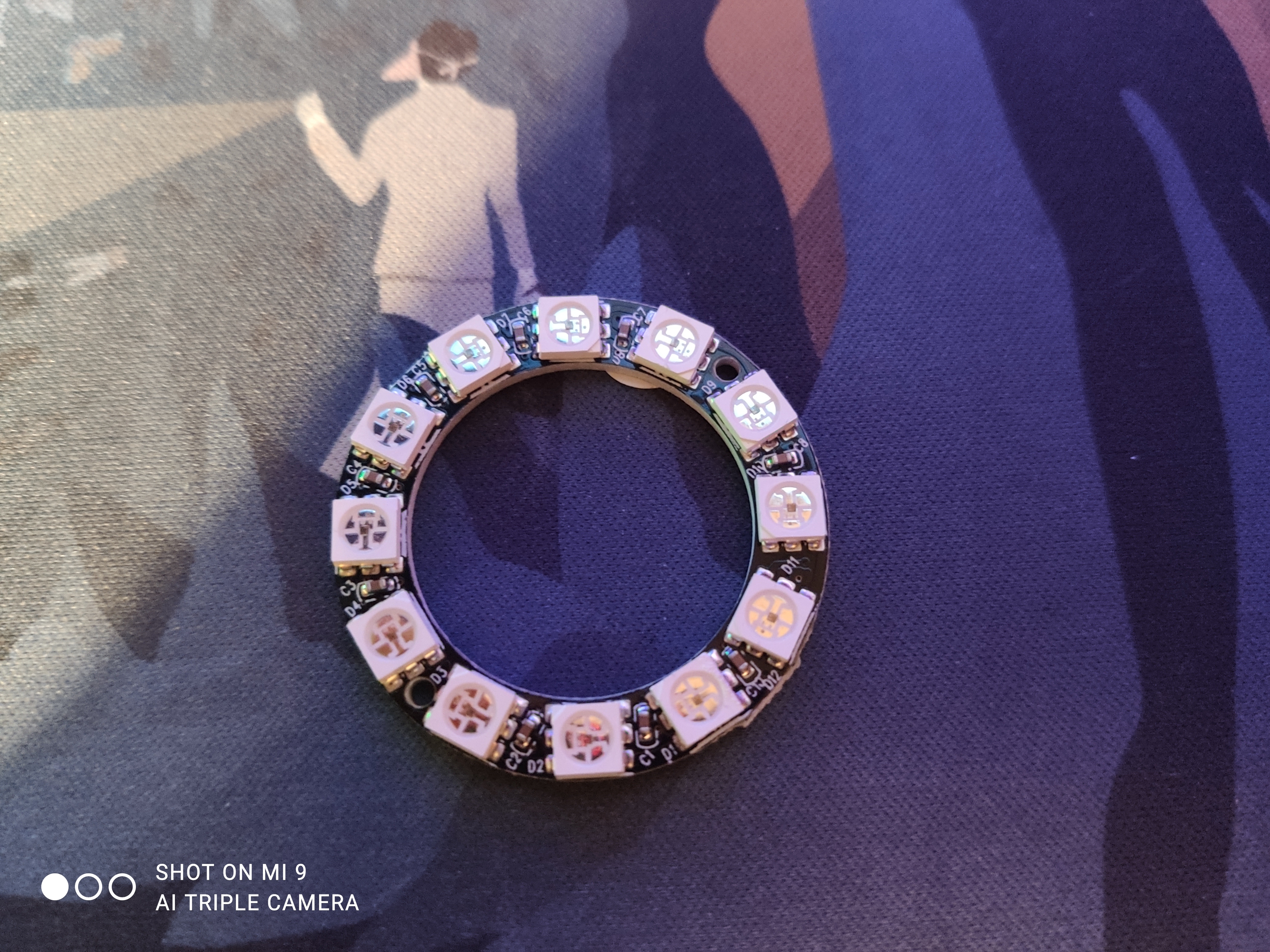
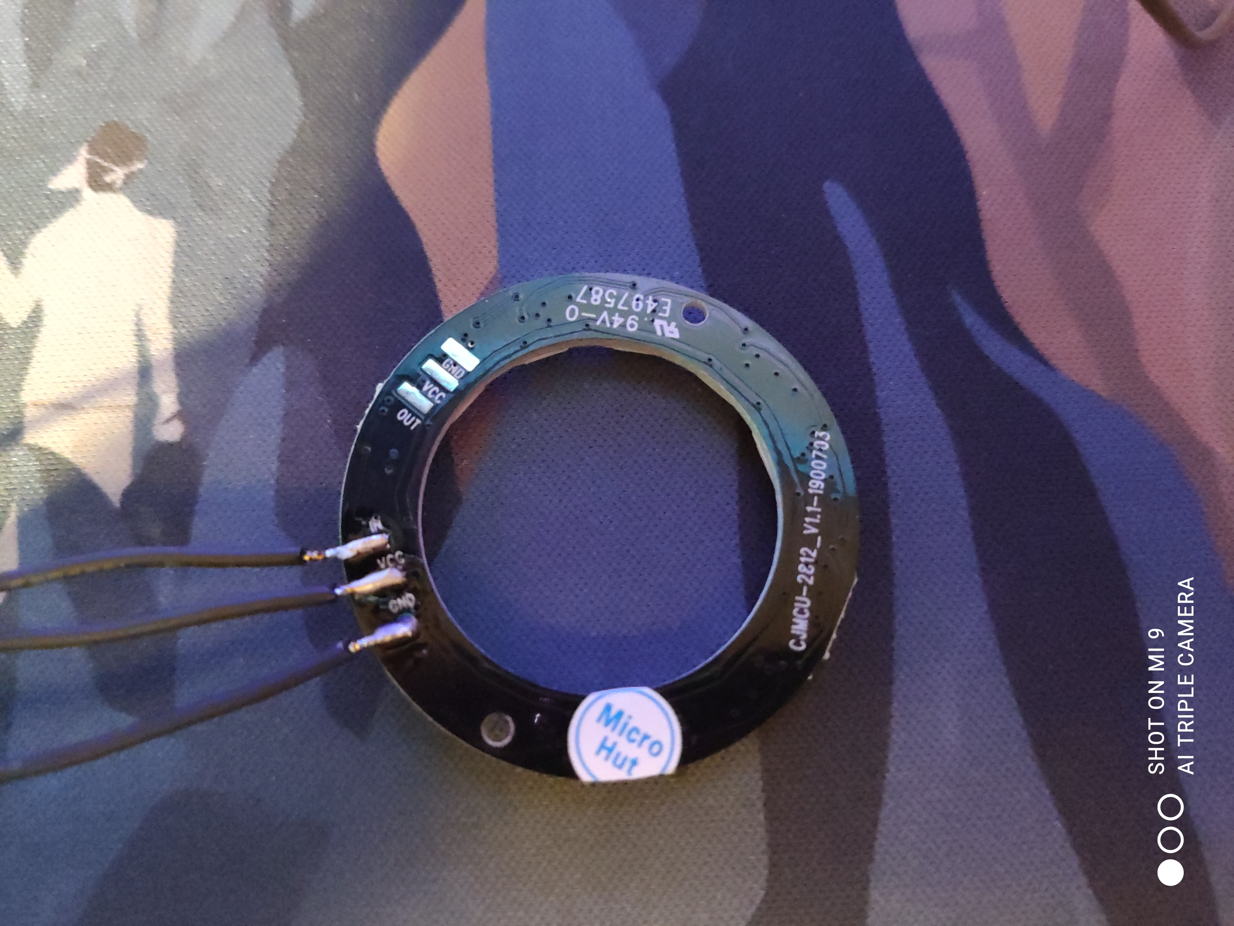
- Add even more LED’s with a neopixel (clone) ring.
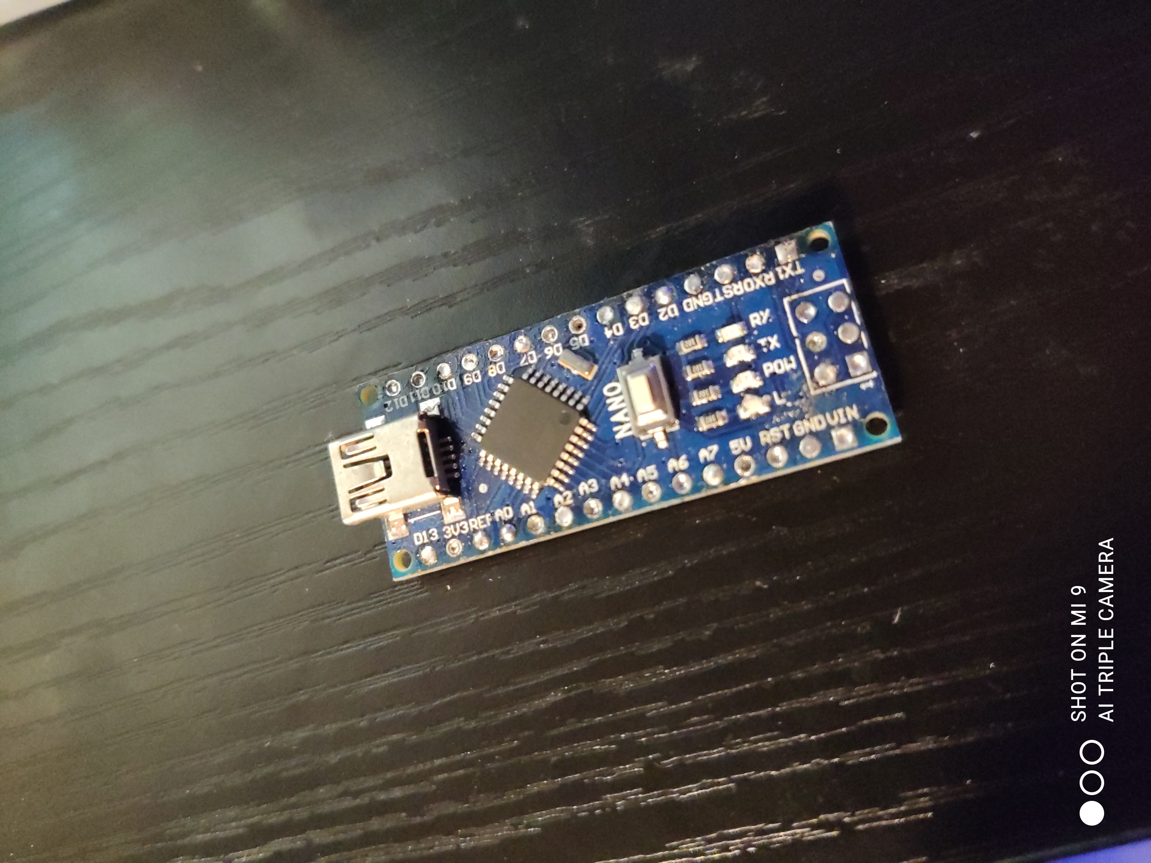
- Add in an Arduino nano to control it all.
Starting Hardware Modifications.
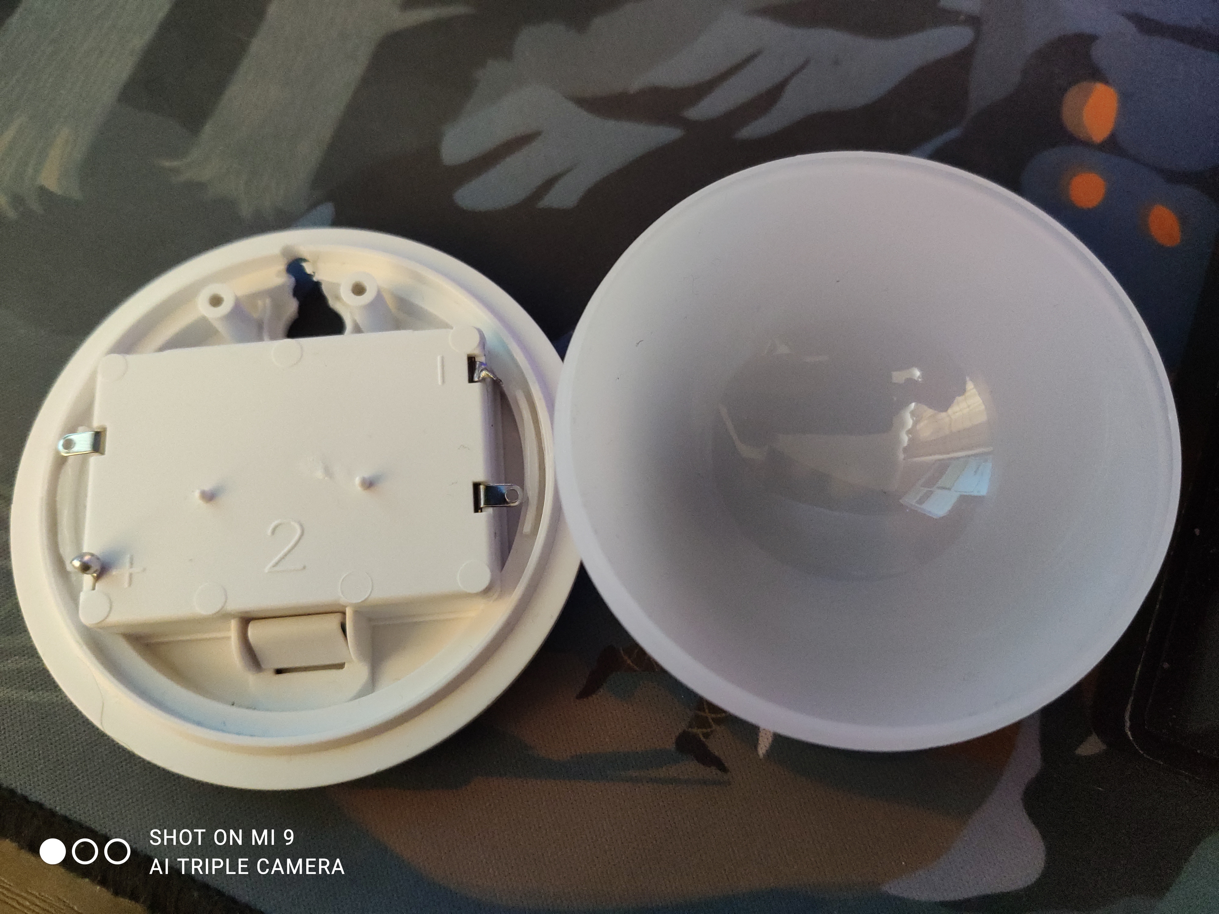
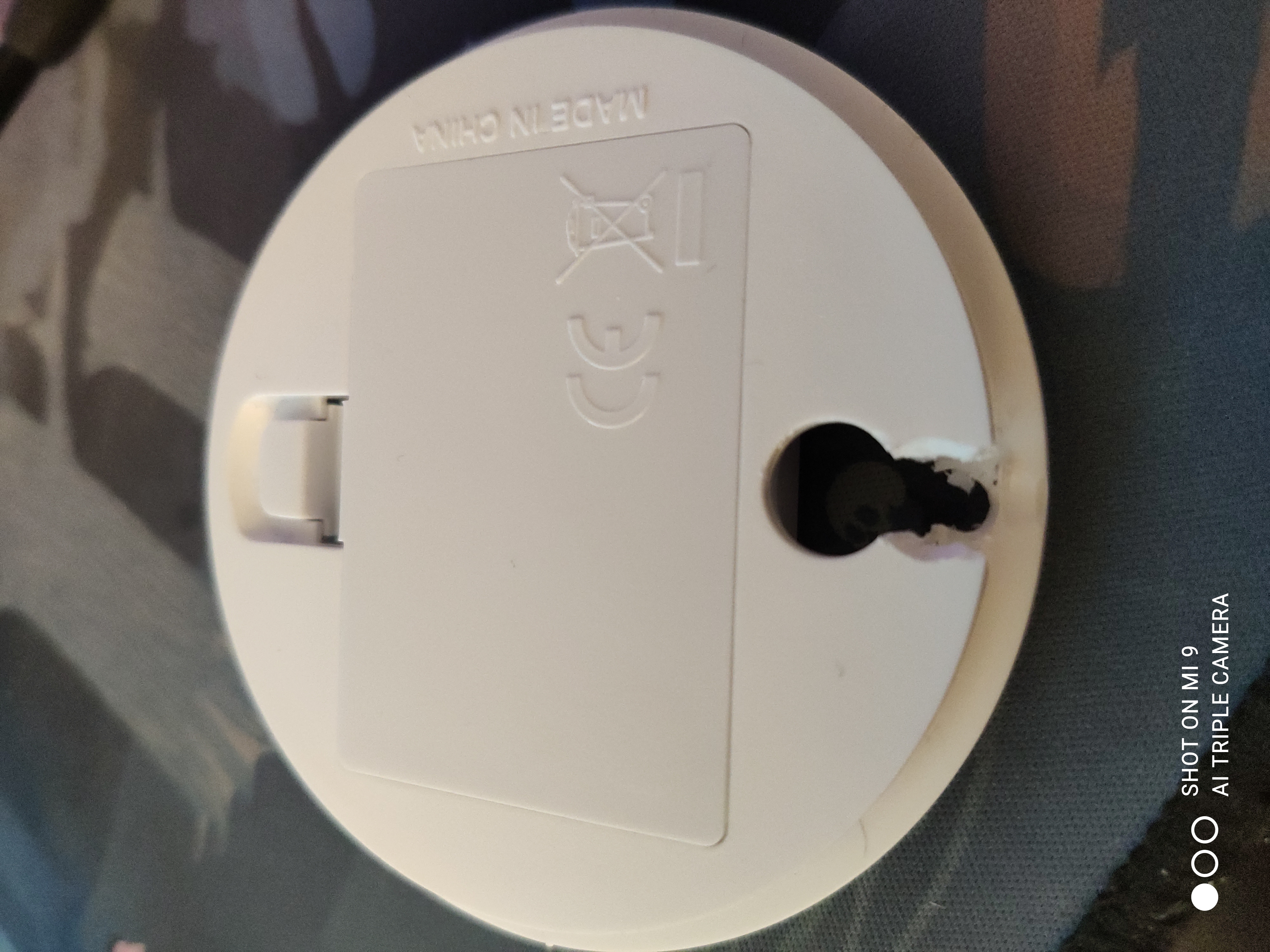
The bottom of the device has very little room for a USB cable to fit as stock. To get around this issue I removed the power button because after removing the original circuit board it’s no longer needed. I used a step drill bit to drill a small hole in which I can guide the USB cable through so it can sit level when the lamp is on a surface as I don’t want it to rock around.
After that was done I prepped the RGB ring for testing.
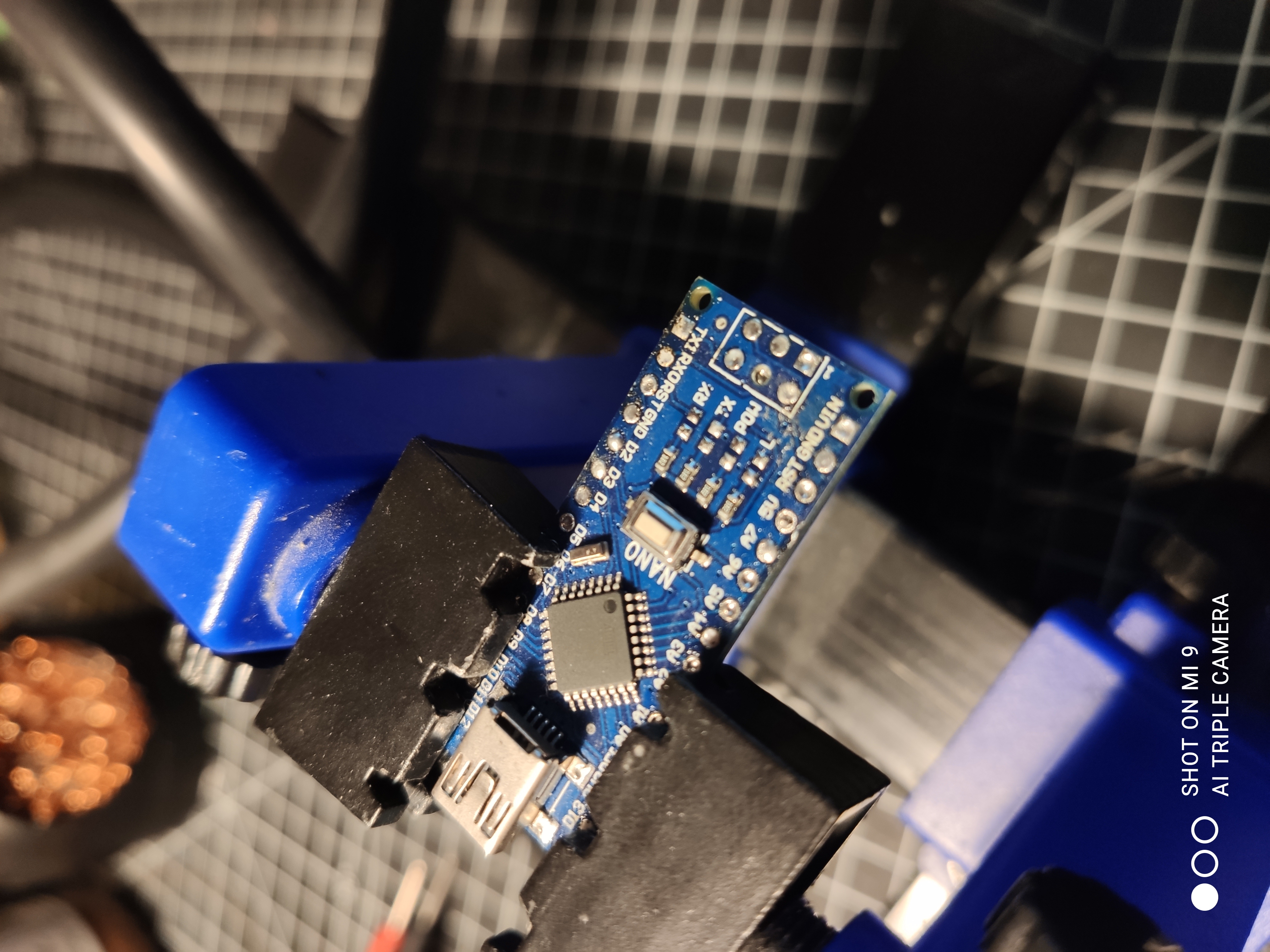
Now that is done I prep the Arduino as the Arduino I bought comes with the pins soldered on. I removed each pin for a low profile as we need to fit components into a tight space.
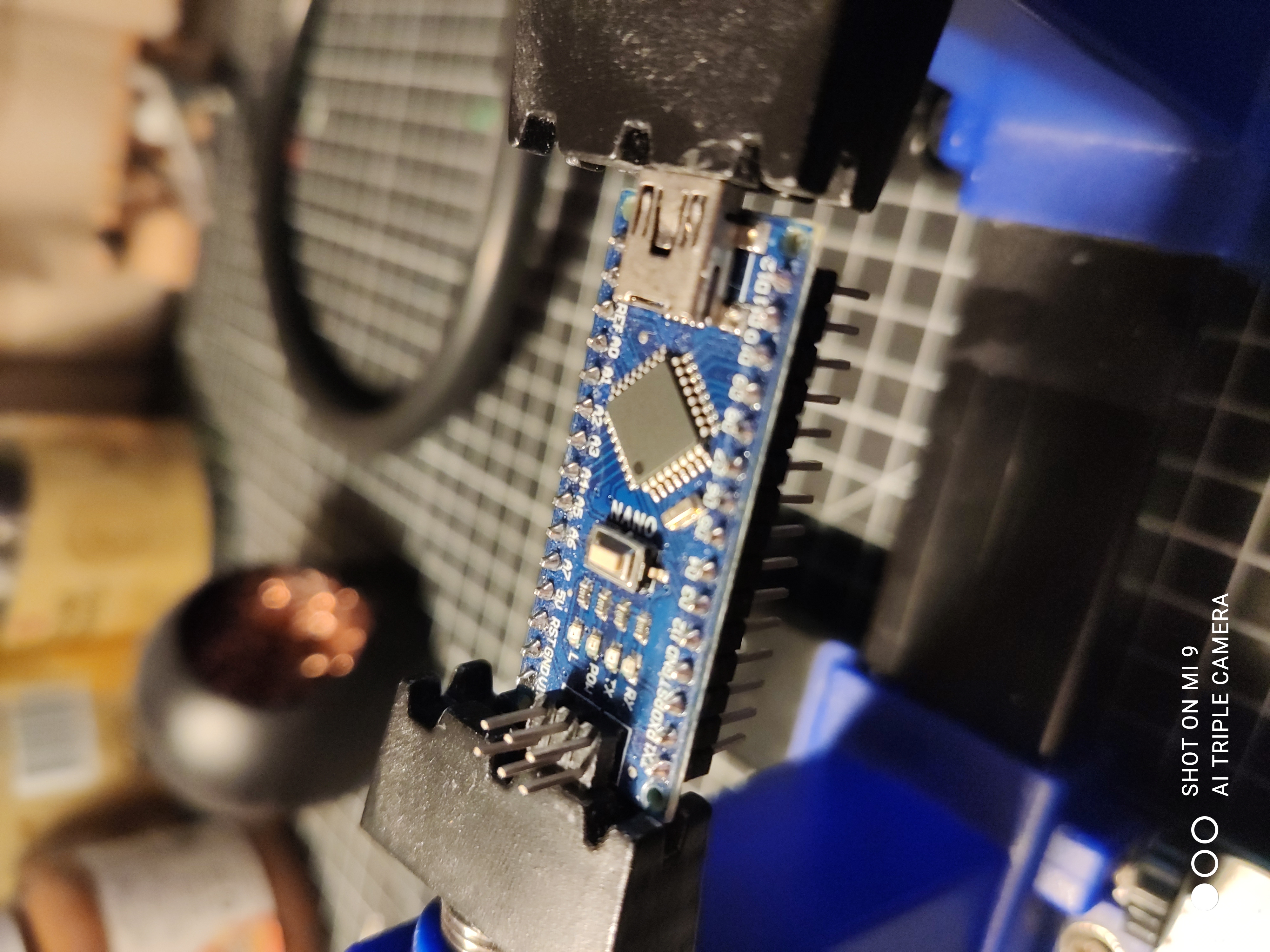
The Arduino nano by default comes with some LED’s onto the board. These tiny LED’s are for power and data transfer as an inidicator to users that the board is doing something. In my case I don’t want the Arduino to have any blinking as it’s going to ruin the lights from the neopixels.
Software
In this sketch I’m using D6 on the Arduino to the ‘IN’ pin and im also using D11 to the data pin on the IR reader.
#include <IRremote.h>
#include <Adafruit_NeoPixel.h>

/* RGB Cat written by Virtual-
   https://blog.tonnochi.net

   IR sensor pinout: Notch facing you:

   Left pin: D11
   Middle pin: GND
   Right pin: VCC

   LED pin: D6

*/

/* Definitions */
#define DECODE_NEC 1
#define LED_PIN    6
#define LED_COUNT 12
int IR_RECEIVE_PIN = 11;
int brightness = 50;
Adafruit_NeoPixel strip(LED_COUNT, LED_PIN, NEO_GRB + NEO_KHZ800);

void colorWipe(uint32_t color, int wait) {
  for (int i = 0; i < strip.numPixels(); i++) { // For each pixel in strip...
    strip.setPixelColor(i, color);         //  Set pixel's color (in RAM)
    strip.show();                          //  Update strip to match
    delay(wait);                           //  Pause for a moment
  }
}

void setup() {
  Serial.begin(115200);
  IrReceiver.begin(IR_RECEIVE_PIN, ENABLE_LED_FEEDBACK, USE_DEFAULT_FEEDBACK_LED_PIN);

  strip.begin();
  strip.show();
  strip.setBrightness(brightness);
}

void loop() {

  if (IrReceiver.decode()) {

    // Print a short summary of received data
    //IrReceiver.printIRResultShort(&Serial);
    if (IrReceiver.decodedIRData.protocol == UNKNOWN) {
      // We have an unknown protocol here, print more info
      IrReceiver.printIRResultRawFormatted(&Serial, true);
    }
    Serial.println();

    IrReceiver.resume(); // Enable receiving of the next value

    /*
       Finally, check the received data and perform actions according to the received command
    */

    switch (IrReceiver.decodedIRData.command)
    {
      case 0x0:
        if (brightness >= 100) {
          break;
        } else {
          brightness += 5;
          strip.setBrightness(brightness);
          strip.show();
        }
        break;
      case 0x1:
        if (brightness <= 5) {
          break;
        } else {
          brightness -= 5;
          strip.setBrightness(brightness);
          strip.show();
          Serial.println(brightness);
        }
        break;
      case 0x2:
        colorWipe(strip.Color(0, 0, 0), 0);
        break;
      case 0x3:
        colorWipe(strip.Color(255, 255, 255), 0);
        break;
      case 0x4:
        colorWipe(strip.Color(255, 0, 0), 0);
        break;
      case 0x5:
        colorWipe(strip.Color(0, 255, 0), 0);
        break;
      case 0x6:
        colorWipe(strip.Color(0, 0, 255), 0);
        break;
      case 0x7:
        colorWipe(strip.Color(255, 255, 255), 0);
        break;
      case 0x8:
        colorWipe(strip.Color(255, 25, 0), 0);
        break;
      case 0x9:
        colorWipe(strip.Color(0, 255, 25), 0);
        break;
      case 0xa:
        colorWipe(strip.Color(25, 0, 255), 0);
        break;
      case 0xb:
        //colorWipe(strip.Color(255, 0, 0), 0); // Flash not in use atm
        break;
      case 0xc:
        colorWipe(strip.Color(255, 50, 0), 0);
        break;
      case 0xd:
        colorWipe(strip.Color(0, 255, 50), 0);
        break;
      case 0xe:
        colorWipe(strip.Color(200, 0, 255), 0);
        break;
      case 0xf:
        //colorWipe(strip.Color(255, 0, 0), 0); // Strobe not in use
        break;
      case 0x10:
        colorWipe(strip.Color(255, 100, 0), 0);
        break;
      case 0x11:
        colorWipe(strip.Color(0, 100, 255), 0);
        break;
      case 0x12:
        colorWipe(strip.Color(255, 0, 100), 0);
        break;
      case 0x13:
        //colorWipe(strip.Color(255, 0, 0), 0); // Fade not in use
        break;
      case 0x14:
        colorWipe(strip.Color(255, 255, 0), 0);
        break;
      case 0x15:
        colorWipe(strip.Color(0, 255, 180), 0);
        break;
      case 0x16:
        colorWipe(strip.Color(255, 0, 200), 0);
        break;
      case 0x17:
        //colorWipe(strip.Color(255, 0, 0), 0); Smooth not in use
        break;
      default:
        break;
    }
  }
}
Assembly.
Assembling the final build I got glued the nano to the base, I chose to keep the USB header on here in case I ever need to re-flash the device at any time.
I routed the USB cable through, snipped the data pins as I won’t need them again and soldered the black to GND and red to 5V. I then secured it with more hot glue.
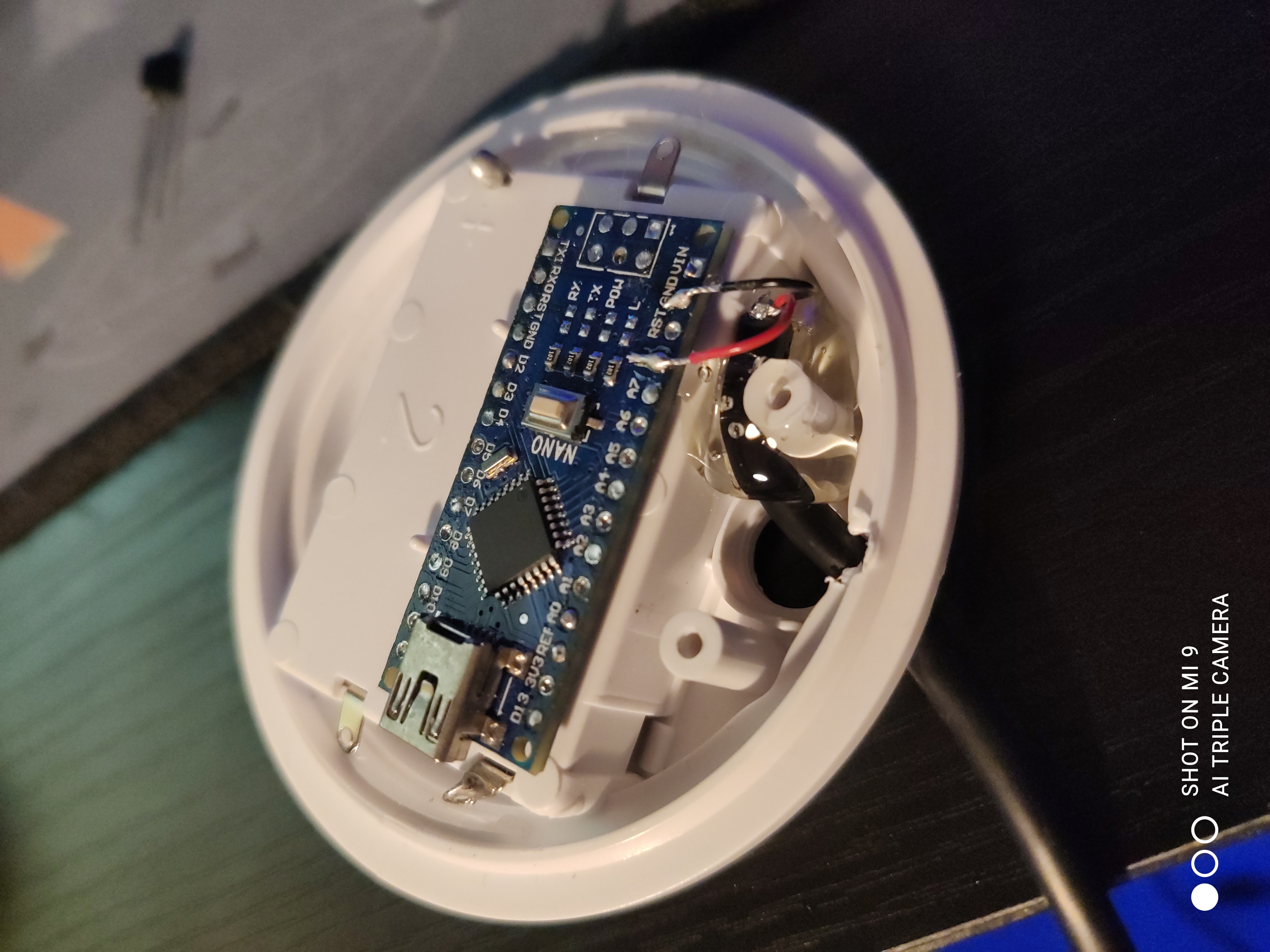
Next I added the IR reciever to the D11 pin with VCC and GND too.
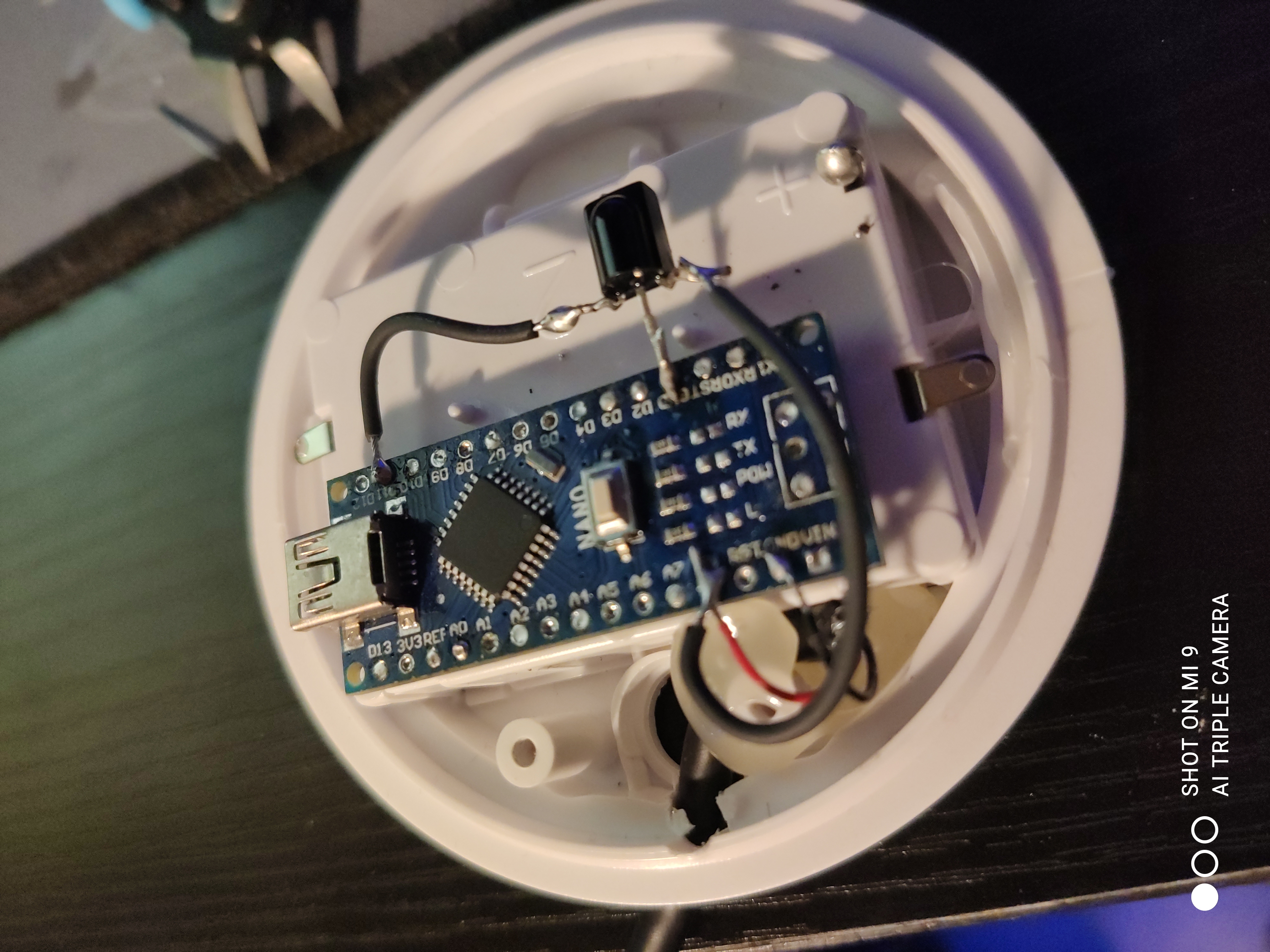
Time for the RGB Neopixel ring to D6, also GND and VCC. At this point I tested to see the device to see if it was still working which it was.
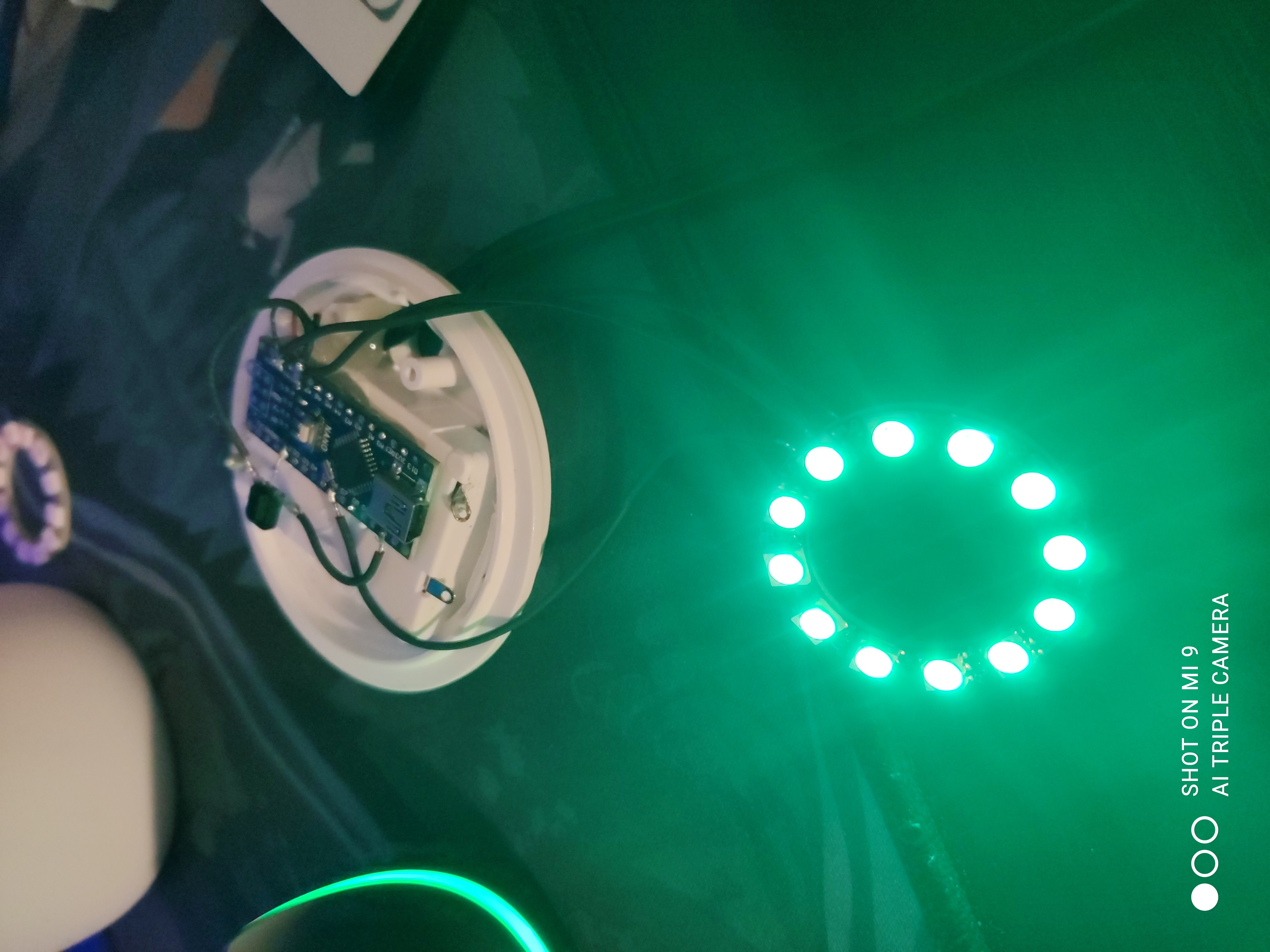
I glued the bottom of the ring to the top of the arduino being careful not to cause any shorts.
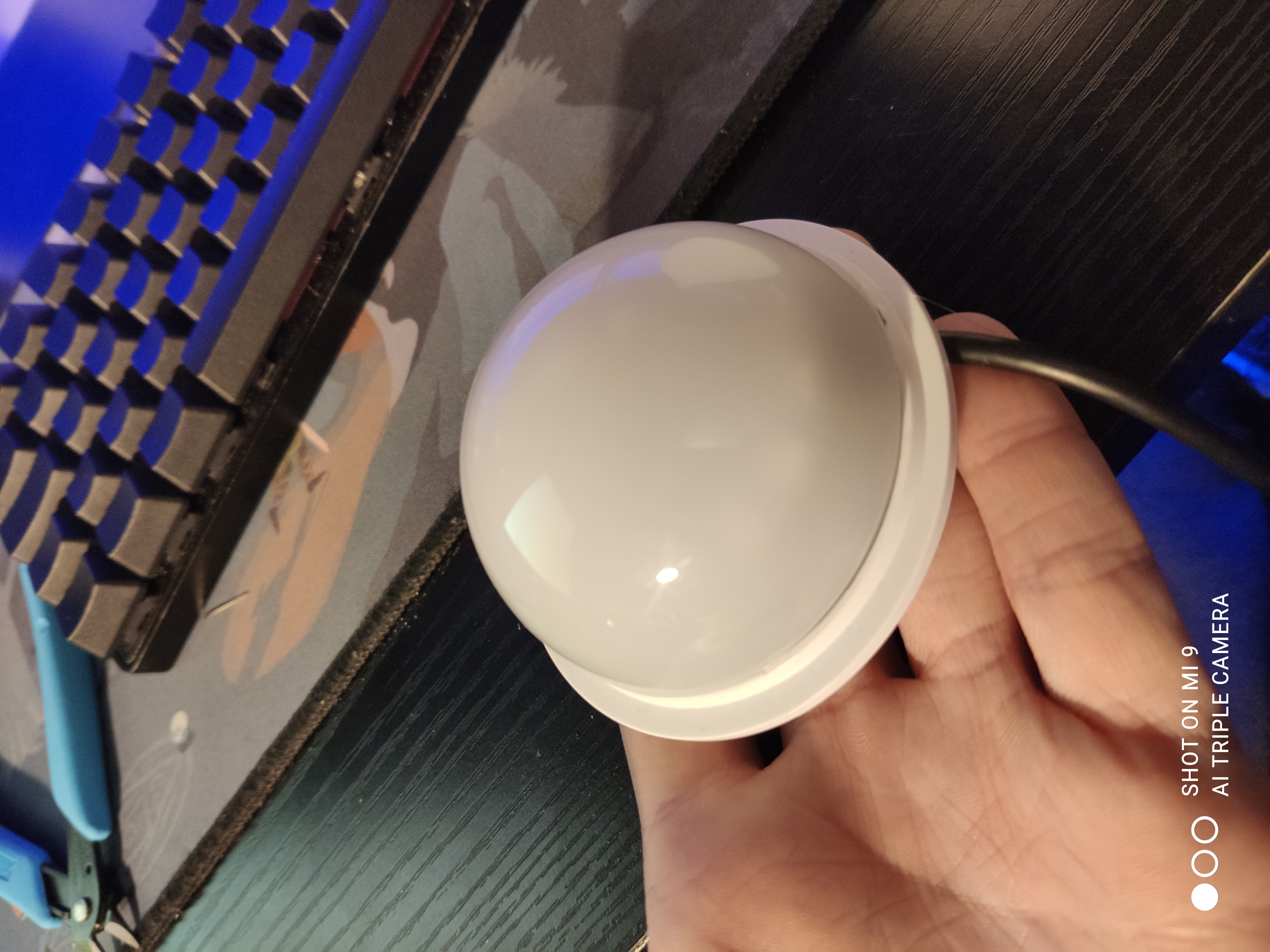
The finished product: